Real Magic: Building Custom Interface Tables with Cameo/Magic Draw and Generic Tables
One of the great things about Model-Based Systems Engineering (MBSE) is that the system model enables us to run all kinds of analyses, for example regarding the consistency, or compliance with company guidelines, to create reports and perform simulations. Often we need to give a detailed overview over the interfaces of a (part of) a system, for example as part of an Interface Control Document (ICD). Magic Draw / Cameo has built-in diagram types for this kind of table (called Blackbox-ICD Table or Whitebox-ICD Table). However, these built-in tables are often not flexible enough or do not cater for the semantics of your custom profile. Therefore, this article shows how to build a custom interface tables Cameo/Magic Draw’s generic tables. This article is more a tutorial, so I encourage you to follow along.
Example Model: The Climate Control System
We will use the model of the Climate control system included with Cameo/Magic Draw as an example for demonstration. You can open the sample model via the Welcome Screen. Choose Samples → Climate Control System to open the example model. The interesting part of the model is located in the package Climate Control Hardware Assembly. The block Climate Control Hardware contains an Internal Block Diagram (IBD) showing the main subsystems of the climate control system. There are further IBDs showing specific views onto the hardware architecture including only selected domains (e.g. electrical).
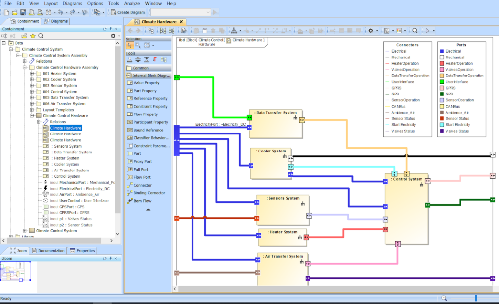
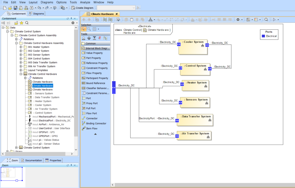
Especially, when architectures get larger, creating such domain-specific views is a good practice. Furthermore, the systems have an internal structure which is modelled in further IBDs. Here is an example of the internal structure of the Cooler System:
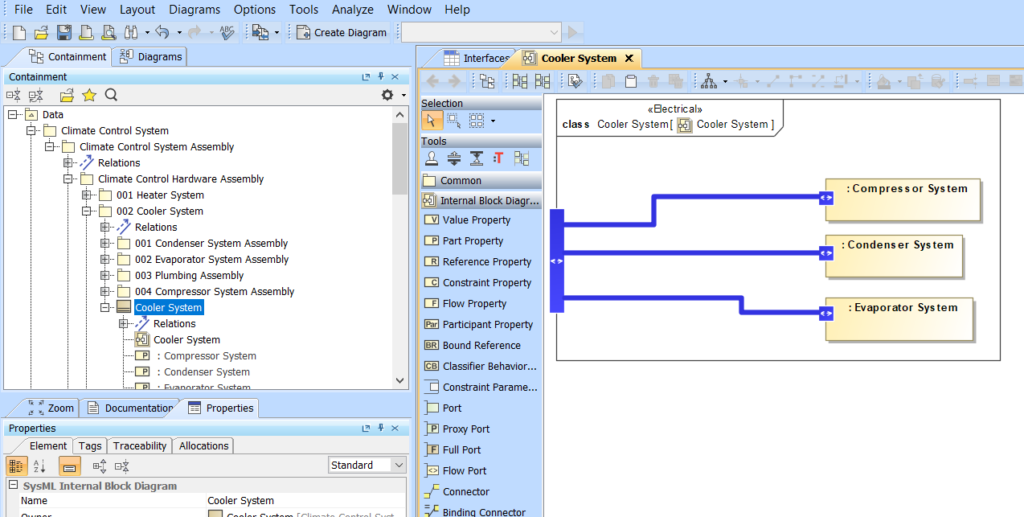
Using the model hierarchy we can drill down into the system and explore its internal structure. The downside is that we lack a central view presenting all involved interfaces. Especially for documents such as an interface control document, we need a table listing all the interfaces.
Quick & Easy: Whitebox ICD Tables
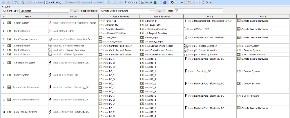
Luckily, Cameo/Magic Draw includes the Whitebox ICD Table, which does exactly what we need. Let’s create an Whitebox ICD Table inside the Climate Control Hardware block (Right-click on the Climate Control Hardware block → Create Diagram → Switch to Expert view → Choose Whitebox ICD Table). Here is the result:
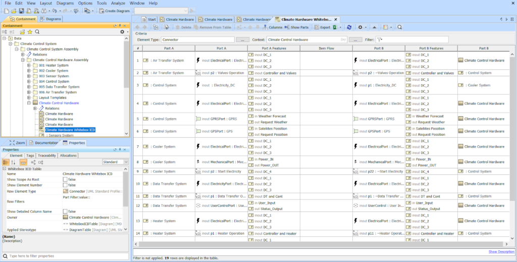
The table contains a row for every connector in the system. This includes delegate connectors from the boundary of the Climate Hardware boundary to an inner part as well as assembly connectors between inner parts of the Climate Hardware block. Each row lists the involved part, port and features (e.g. flow properties of the associated interface block of a port) for each end of the connector. This is pretty neat and the effort to create the table is minimal. However, there are a few caveats. Most importantly the Whitebox ICD table can hardly be customized. For example, depending on the use-case, we might not be interested in the interfaces between inner parts and the outer block, but only in the interfaces between the hardware systems (e.g. Cooler System and Control System). Furthermore, we might be interested not in the interfaces between the systems but instead look beyond the system boundary and show the interfaces between the subsystems. The Whitebox ICD Table doesn’t provide that information. But there is no reason to worry. Cameo/Magic Draw has a powerful tool for us to assemble a suitable table. The tool is called “Generic Table”.
The Swiss Army Knife: Generic Table to the rescue
The Generic Table is a versatile tool for displaying model information in a tabular way. We can use it, If we need more control over what information exactly to display, compared to a Whitebox ICD table. Let’s create a Generic Table and work our way towards a more refined ICD table.
Recreating the Whitebox ICD Table with a Generic Table
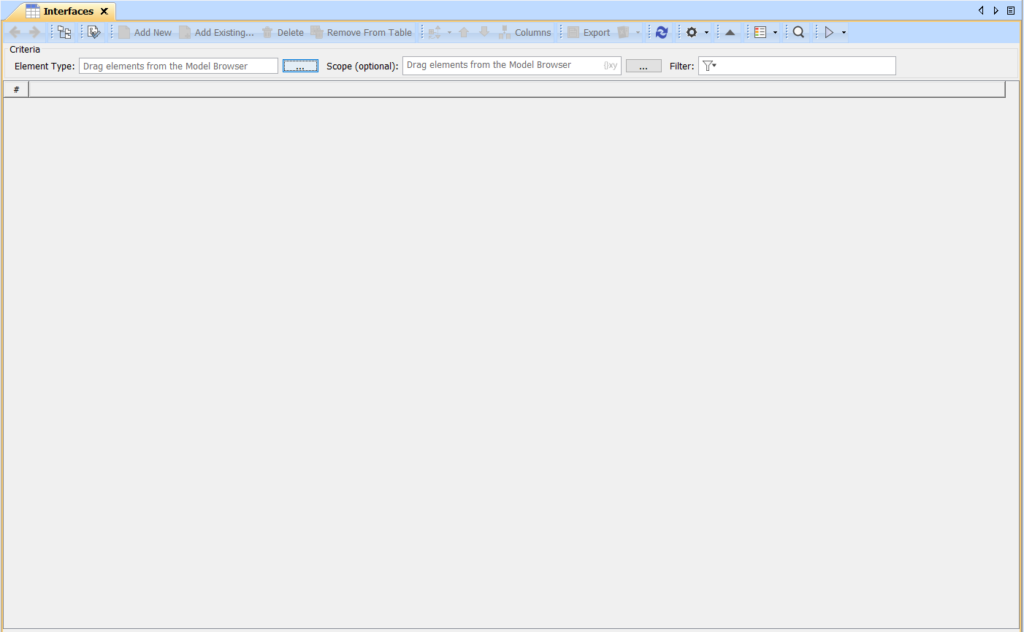
As a first step we create an empty table. I often create a specific top-level package where I collect all my reporting tables. Wherever you created your package, bring up a Create Diagram dialog (e.g. via right-click on the package → Create Diagram) and select Generic Table. Here is what you get: an empty table.
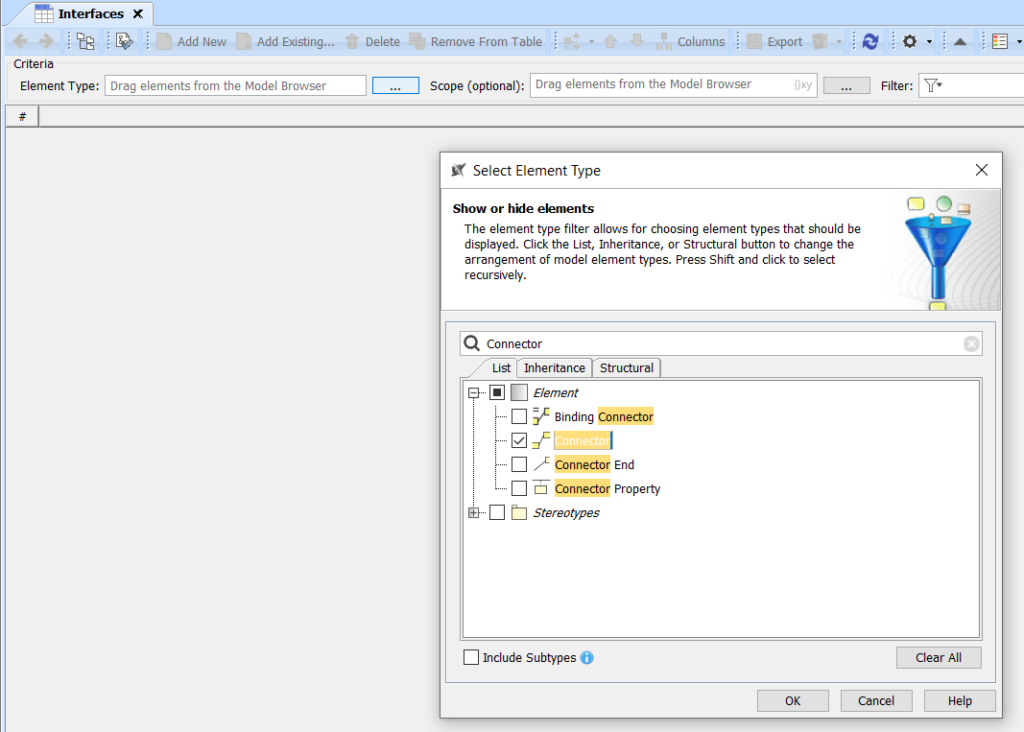
As the first step, let’s recreate the Whitebox ICD table using the generic table. Therefore, we first have to select which element type we want to display in the table. Each row of the table will then represent one element of that type. In our case, we choose Connector as element type, as it is the case in the Whitebox ICD table. For that, select the “…” button besides the field labeled “Element type” and in the upcoming dialog choose the Connector element type.
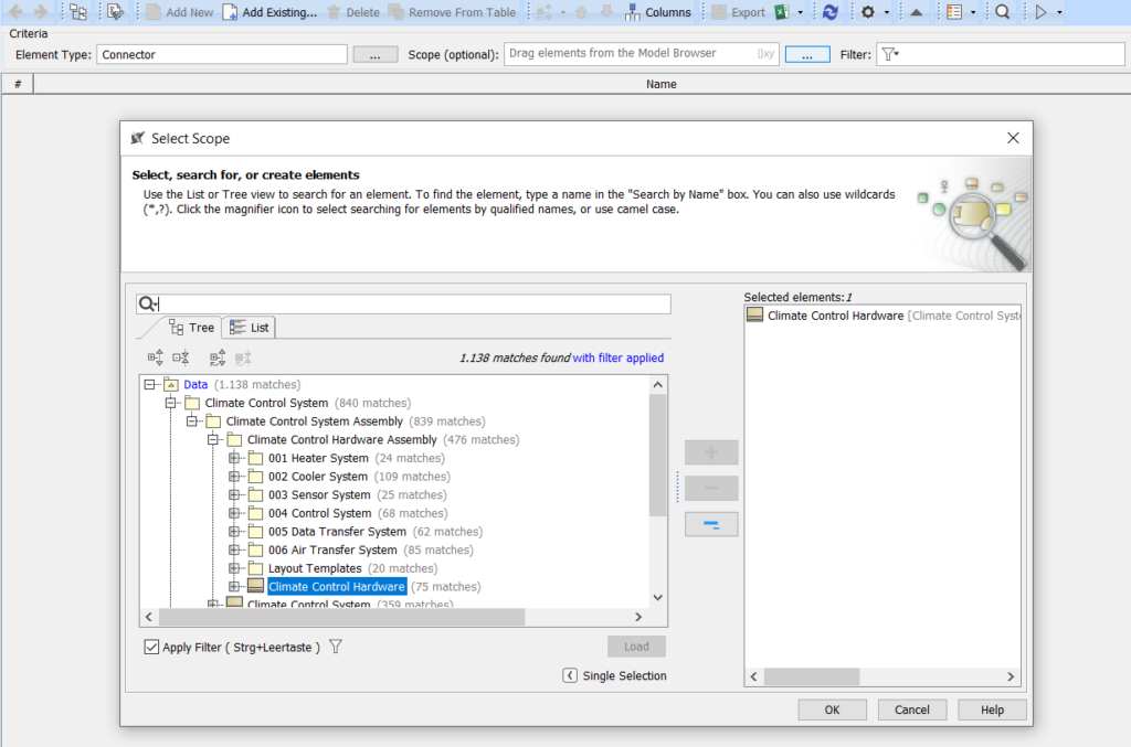
After selecting the element type, the table is still empty. We first need to define a scope in order for something to be displayed. For that, select the “…” button besides the field labeled with “Scope”. In the upcoming dialog, navigate to the Climate Control Hardware block and add it to the selection. Be sure to remove any other element from the selection.
Configuring Standard Table Columns
Now, for the first time, the table actually shows something. However, the result is pretty useless, as we only see empty cells. The reason is that up to now, we only show the name attribute of the connector, which is empty for all the connectors in scope. Let’s remedy that and add some columns. You can add columns to a generic table by clicking on the “Columns” button in the toolbar and check the attributes that you want to show as columns. For example, you could select the Role columns (there are two, one for each connector end) to display the ports of the connector. The problem is, that we cannot change the name of the connector in this case. Therefore, we opt to create a custom column.
Configuring Additional Custom Table Columns
Before we do that, let me explain the difference between a “Custom Column” and a “Derived Property”. You see both options at the bottom of the “Columns” menu and from the perspective of the table there seems to be no difference. However, the difference is that when you create a derived property you are effectively adding a new attribute to the meta-class of the element type (Connector in our case) and you can use this new attribute outside of the generic table throughout the whole model. Whereas a custom column is only visible inside the table. Furthermore you can use derived attributes to define further derived attributes or custom columns, which you cannot do with custom columns.
For all of the following we need to differentiate the two ends of the connector. Before, we saw that in the columns list of the generic table we can select specific columns for each end of the connector. However, these columns seem to be unavailable for defining custom columns. Therefore, we create two derived properties, one for each connector.
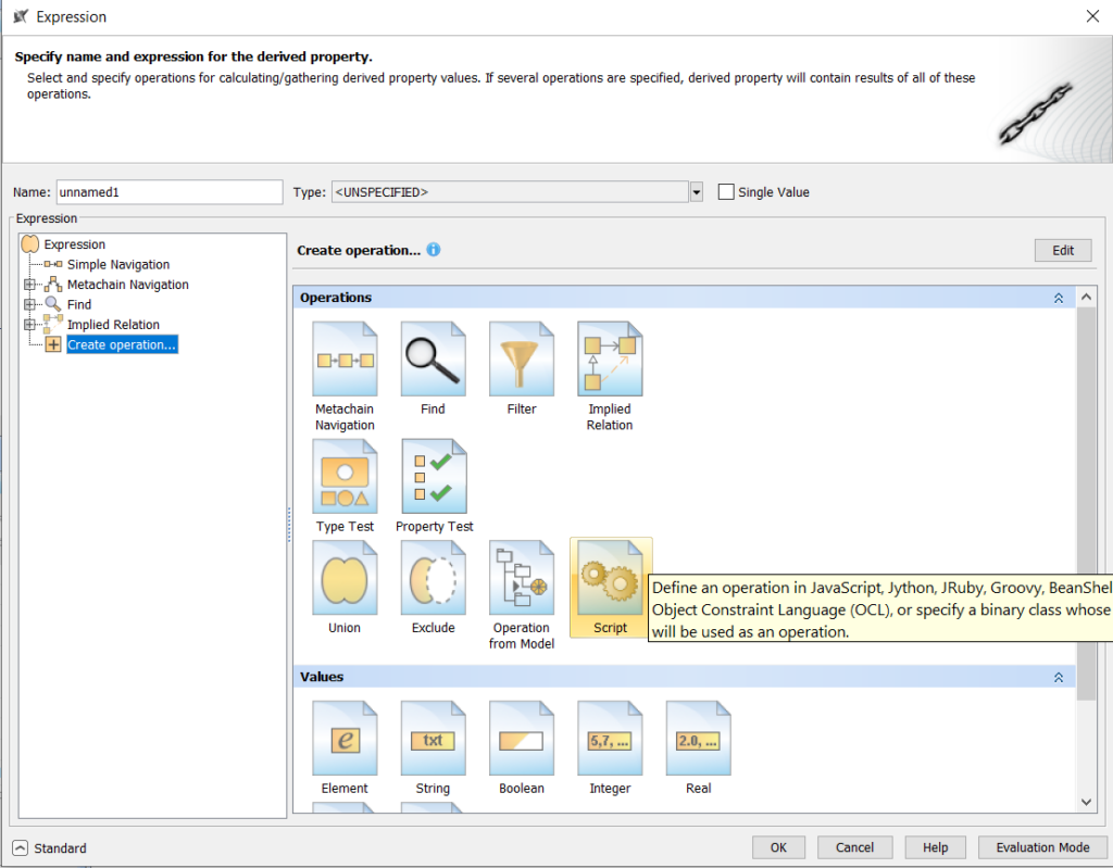
For that, choose “Columns” (in the toolbar) → “New Derived Property”. What you see now is a very powerful tool named the expression editor. You might know this tool from other parts of Cameo/Magic Draw. It is used in many places where you need to define some kind of query. In fact it is a collection of different tools, some of which we will explore in this article. What we are going to do now, is to define an OCL script. For that, activate the Export Mode (bottom left of the dialog), choose “Create operation…” in the Expression tree and select the Operation type Script in the operation palette (right part). See also the figure below for what to find where.
This will open up the script editor where you can define queries in a formal, text-based way using different scripting languages. In our example we will use OCL (Object Constraint Language). Here are some details on using OCL in Magic Draw and a detailed description of the language.
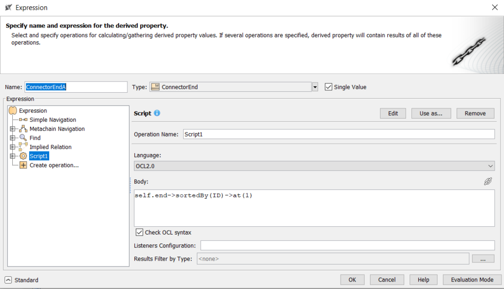
To use OCL as a scripting language, choose “OCL 2.0” from the “Language” dropdown menu. In order to select one specific end of the connector, enter the following text into the text-field below:
self.end->sortedBy(ID)->at(1)
Let’s disassemble this in order to understand what’s going on:
selfrefers to the specific element instance that is our context. For us this is the instance of a connector.self.endrefers to the ends of the connector. Although it is written in singular, this expression results in all the connector ends.self.end->sortedBy(ID)returns the two connector ends in a defined order, namely ordered by their internal idself.end->sortedBy(ID)->at(1)finally is the first of the two connector end, as defined by the sorting order
That’s basically it, all we have to do is to give our derived property a name (“ConnectorEndA”), select the type of the result (ConnectorEnd), and check the “Single Value” box to specify that this property only returns only a single value. In the figures below you see the final result. If you close the dialog the generic table will update and show the new derived property in a new column. Repeat the same for the other end of the connector, only this time the OCL reads self.end->sortedBy(ID)->at(2) (“2” instead of “1” to select the second connector end), but you probably have guessed this already.
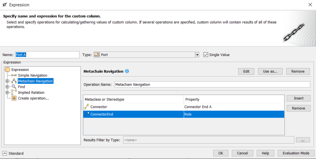
Now, we are in a good shape to define the other columns to achieve our first goal: rebuilding the Whitebox ICD Table. To define the missing columns, we could again use OCL scripts. However, we use a simpler tool, called “Metachain Navigation”. First we create a new column (“Columns” → “New Custom Column…”). In the upcoming expression editor, select Metachain Navigation on the left side in the expression tree. Now define a navigation path to a port of the connector, as shown in the figure below. Note that we use the derived proper ConnectorEndA in the first step. Finally choose a name for the column (e.g. “Port A”), specify the type (Port) and check the Single Value checkbox. Needless to say, that a Port B column is defined in an analogous way.
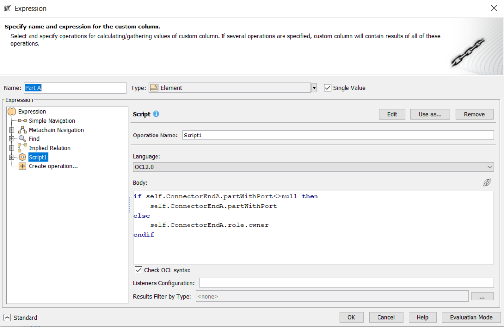
Next, we specify the column showing the part (or block in case of a delegate connector). This one is a bit more complicated as we have to handle the two cases. Consequently, we again use OCL for this task. The according script is the following:
if self.ConnectorEndA.partWithPort<>null then
   self.ConnectorEndA.partWithPort
else
   self.ConnectorEndA.role.owner
endif
Let’s break it down a bit:
- The expression
self.ConnectorEndA.partWithPortresults in the part corresponding to the connector end. This expression evaluates to the value null if the connector ends at the block boundary. - Therefore, In the first line we check whether the part is not null (
self.ConnectorEndA.partWithPort<>null) and only then return the part. Otherwise we return the owner of the port (self.ConnectorEndA.role.owner).
To finalize the column definition give it a name, specify Element as type (as the result can be both a part or a block) and check the single Value box.
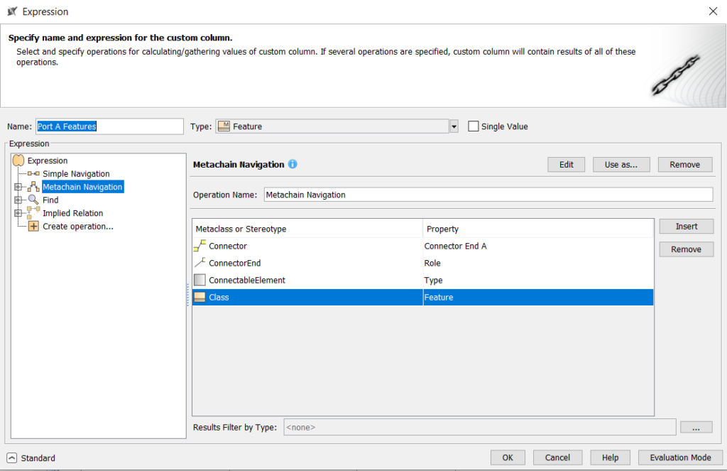
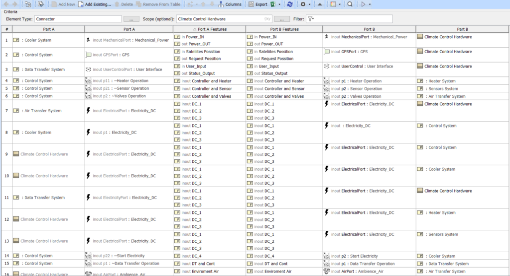
We have one more column to go for our intermediate goal. The last column in the ICD table shows the interfaces features. Again we use a Metachain-Navigation for the definition. See the figure below for details.
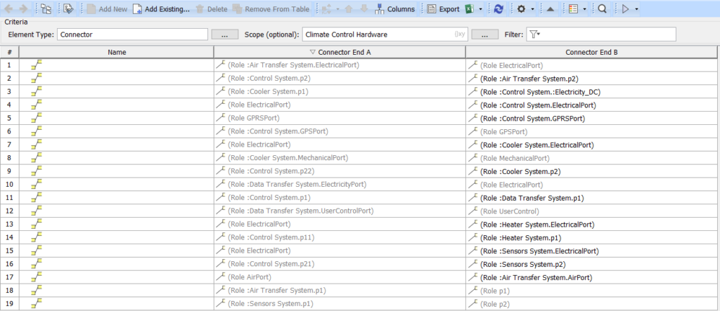
Here we go, we have all columns in place for our custom Whitebox ICD Table. Let’s hide the unnecessary columns (Name, Connector End A/B) by right clicking on the column header and selecting “Hide” and arrange the columns. Here is the result:
Customizing the Interface Table Scope
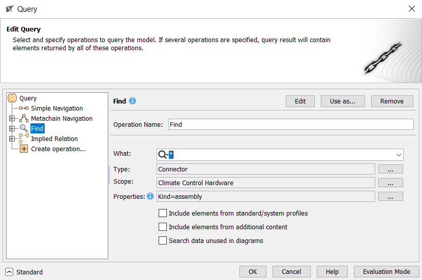
So far, we just rebuilt the Whitebox ICD Table, now we are going to customize it. The first thing we will change is the scope of the table. Assume we are only interested in the interfaces between the systems of the Climate Control Hardware (and not the interfaces between the systems and the Climate Control Hardware boundary. In order to concentrate on these interfaces we have to change the scope of the query that defines the table’s content. Recall that we set the scope simply to the Climate Control Hardware block. We have to change that. In order to do so, click on the “{}xy” symbol in the scope field. The expression editor comes up. This time, we can use a “Find” expression to define our scope. Choose the “Find” query type on the left side. On the right side of the editor choose Connector as type, Climate Control Hardware as Scope and select the “kind” property to have value “assembly” in the “properties” part of the form. See below for a summary of how to fill the Find form. You can switch on Evaluation Mode (bottom right of the dialog) to verify the result.
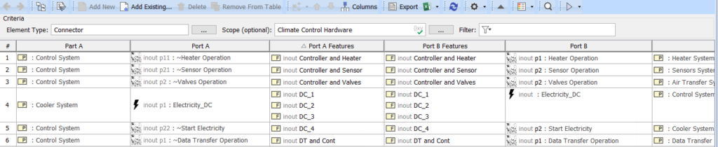
Back in the table we are left with only six rows:
Adding more magic: Displaying Connected Subsystems
We are going to add one more type of column showing the connected inner subsystems. Unfortunately, in the example model, most of the inner connections to the subsystems relate to ports of the systems that are themselves connected to outer ports of the Climate Control Hardware block and therefore excluded from our refined scope. However, we can later again broaden the scope of the table to see more results.
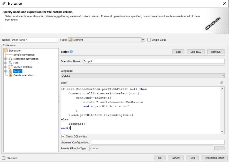
We create a new column “Inner Parts A” that will display the inner parts connected to the port displayed in the column “Port A”. There seems to be no direct way to navigate from an outer-connector to the inner-connectors of a port. Therefore we need to create a somewhat complex expression to achieve our goal. In the expression editor for the column create a new OCL script (remember to activate the export mode, then select “Add Operation…” in the query tree and finally select “Script” on the right panel). The OCL script we need, is the following:
1  if self.ConnectorEndA.partWithPort<>null then
2      Connector.allInstances()->select(conn|
3            conn.end->exists(e|
4                e.role = self.ConnectorEndA.role
5            and e.partWithPort=null
6            )
7    ).end.partWithPort->excluding(null)
8  else
9    Sequence{}
10 endif- In line 1 we have our familiar check, that the connector ends at a part and not at the outer boundary of the containing block.
- Lines 2 to 5 formulate a query over all connectors. Essentially, we look for a connector which is connected to the same port (line 4) but from the inside (line 5).
- From those ports we collect the connected parts, that means the subsystems (line 7).
- In case the connector ends at the block boundary, we just deliver an empty sequence (line 9). Here is the final result in the editor:
EDIT: A reader (Thank you, Udo!) pointed out that performing Connector.allInstances() can be a performance bottleneck in large models. An improvement is to replace Connector.allInstances() by self.ConnectorEndA.partWithPort.type.ownedElement->select(e|e.oclIsKindOf(Connector)).oclAsType(Connector), which will not select Connectors globally but only the relevant ones from the type of the part at the connector’s end.
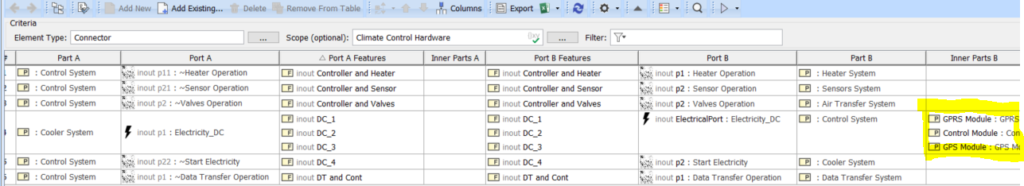
Let’s look at the results in the table. In fact, there is only one case where this column is not empty. In all other cases the example model does not contain any internal wiring, at least not for interfaces between the subsystems.
Summary
In this article I showed you different ways to obtain an interface table in Cameo/Magic Draw. The easiest way is to go with the built-in Whitebox ICD table. However, there might be cases where you need a custom variant of such a table. For that you can use generic tables and define custom columns. I showed you how to rebuild your own Whitebox ICD table from scratch and then customizing it with a more refined scope and an additional column to show the connected inner subsystems.
Contact
If you feel, this article was helpful, or if you have comments or suggestions, drop me a message in the comments section or via maximilian.junker@qualicen.de
I am a consultant for MBSE, if you need support in your MBSE project, me and my colleagues at Qualicen are happy to help. In this case, also feel free to write me an e-mail. You can also find more information about Qualicen and systems engineering at https://www.qualicen.de/systems-engineering/