Getting Started With the SPES System Modeling Framework
We observe that numerous cyber-physical systems are rapidly gaining functionality and thus development gets more and more complex. Innovations are made possible in many areas by a complex interaction of sensor systems and software. Consider the development of autonomous driving, in which a multitude of different system functions must interact safely with one another in order to make complex decisions with the highest quality in order to transport people safely. In order to master the complexity, the classical, document-centered approaches of system engineering are no longer sufficient and are increasingly being replaced by model-based systems engineering (MBSE) approaches.
The SPES modeling framework provides a comprehensive, tool- and modeling language-independent method for MBSE. It offers a whole range of concrete models, modeling techniques and activities. In this blog post, I will introduce you gently to SPES. I will explain the basic principles of SPES and give some pointers where to find more.
From documents to models
A classical way to describe systems is via documents. In order to describe a complex system such as a car, we typically need hundreds of documents. Starting with some high-level goals for the next model, people work their way towards detailed component specifications. Most of these documents is text. Additionally the specifications may include diagrams or figures, maybe even some models to describe the architecture or the behavior of the system or its components. In order to understand the interrelationships between parts of the documents, the authors use links between single items of the document. In the end, we have a set of interlinked documents. Text always bears the risk to be wrongly interpreted. Hence requirements in natural language are inherently ambiguous. Furhtermore, there a certain things we cannot easily do based on such a description, e.g. answer questions like “Does the interfaces between component A and B fit together?”, or “Which functions influence function X?” Also we cannot run a simulation based on this description.
Entering MBSE. The core idea of systems modeling is instead of describing, what things are there, create model elements for them. Hence, we create model elements for subsystems, functions, components, interfaces, etc. Instead of describing which things belong together, we create model elements for the relations (such as the communication via an interface). When we look at the system description, it doesn’t look like a set of documents anymore, instead it is an interwoven net of model elements forming a common whole – the system model. Transitioning from text to models brings the advantage of reducing ambiguities. The more formal the model that you use, the less ambiguity you have in your description.
Where to start?
Getting started with MBSE is not always easy. Often, people tend to think MBSE = SysML, but SysML is a modeling language and not a modeling method. It is a bit like saying: “You want to specify a car? That’s easy, just use English”. Another misconception is to equate MBSE with a modeling tool. The point is, SysML and the modeling tools provide mulitple very general concepts and diagram types but which of them you use and what you describe with them, and how you put this into a process is still up to you. And deciding this is the hard part.
Often, it is not a good idea to start from zero to one hundred in one shot. Moving to MBSE is a big change that can easily overwhelm people. A better strategy sometimes is to move forward incrementally. Start with modeling the architecture, and move in direction to functions and requirements could be an approach. But to develop such a strategy you need to have a map telling you what the increments are and how the relate to each other.
I need guidance – frameworks to the rescue!
Giving you guidance with your modeling method, that means, deciding what to model and what do with the models, is the job of a modeling framework. There are several examples of modeling frameworks for MBSE, for example IBM Harmony [1], SysMod [2] or SPES[3]. A modeling framework usually defines the artefacts that can be described with models (e.g.. a functional architecture), description techniques how to model the content of these artifacts (e.g. function hierarchies), the semantics of these description techniques, and further methods to create or analyse the models.
In this article I want to show you the framework SPES. The acronym is short for Software Platform Embedded Systems. Although SPES is today a full-fledged systems engineering approach the acronym shows it roots in the software domain, and this is still one of its strengths. The main difference between SPES and frameworks such as Sysmod is that it is modeling-language- and tool-independent, hence it is not focused on a specific language like SysML (while SysML is an absolutely valid choice) or a specific tool (as IBM Harmony does).
The SPES Modeling Framework
The SPES modeling framework comprises a large set of models and methods for different contexts and purposes. However there are three core principles that apply to all of them.
- Principle 1: Interfaces everywhere
- Principle 2: Three core viewpoints on the system
- Principle 3: Levels of granularity
Principle 1: Interfaces everywhere
The core principle in SPES is that everything relates to an interface. No matter if we are talking about a function, or a component, a scenario or even a requirement. Every model relates to an interface over which the model can be related to other models. In SPES there is a rather broad notion of interface. It means the syntactical interface (i.e. input and output ports and their types) as well as its interface behavior (i.e. how the outputs are influenced by the inputs). As we are talking about systems inputs and outputs can be digital information signals but also physical energy or material flows.
Principle 2: Three core viewpoints on the system
The second principle is that SPES defines three core viewpoints on the system. A viewpoint relates to certain aspects in the development proces and defines the models and methods necessary to describe that viewpoint. The three viewpoints in SPES are:
- Functional Viewpoint: The models in the functional viewpoint describe the system from a purely functional perspective (i.e. the system as it can be observed from the outside). They leave out technical are architectural details and focus on the functionality of the system and how the different functions relate to each other. In the functional view SPES distinguishes between black-box models that describe system functions that are located at the system interface and white-box models that describe the inner structure of system functions.
- Logical Architecture Viewpoint: The models in the logical architecture viewpoint describe the structure of a system but in an implementation agnostic way. Hence, a component in a logical architecture (e.g. a brake) may later be realized as a purely mechanical component (via a cable) or as a mechatronic component (via brake-by-wire). Models in this viewpoint are hence still independent of a certain engineering discipline.
- Technical Architecture Viewpoint: Models in the technical architecture now are implementation and discipline specific. There may be models describing the geometric properties of a mechanical part, but also models that describe the task architecture of a software application. Important is that the notion of an interface carries over to the discipline specific models and enables the integration of these models.
In fact, there is a fourth viewpoint, the requirement viewpoint. This viewpoint is special as it overlaps with the other viewpoints. It contains models describing the context of the system and requirements to the system. The context elements and the requirements themselves may relate to all the other viewpoints.
Principle 3: Subsystems and components on different layers of granularity
In short, the last principle states that any component in the logical or technical architecture can be seen as a subsystem and treated in the same way as the super-system. That means we can focus on this component and use the SPES methods to engineer it (e.g. the different viewpoints). Sucessively identifying subsystems and putting it in the focus of the engineering defines the layers of granularity (system, subsystem, subsubsystem, etc.). In fact, for every layer N we get several instances of layer N+1, one for every subsystem in layer N. As we define discipline-specific components in the technical viewpoint we can split up discipline specific development branches by moving a technical component to the next layer of granularity.
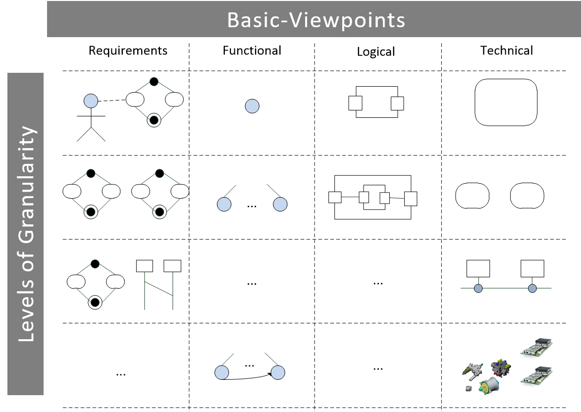
All-in-one: The SPES Matrix
An intuitive way to illustrate the principles is the SPES matrix. It visualizes the viewpoints as columns and the layers of granularity (as rows). For every cell in the matrix, SPES suggests a range of models to describe the necessary information. Mind that SPES does not prescribe a process. Hence you need not (and should not) fill out all the rows from left to right, and jump to the next row when you are finished. Instead there several possible paths through the matrix. And most probably you will adopt an incremental and iterativ approach where you proceed from roughly described models to more detailed ones.

Tooling for SPES
The good news is: With basically every modeling tool you can start using SPES right away as its concepts are tool-independent. However, in order to have the SPES terminology displayed in the tool and to make use of advanced analysis methods you need a bit more. There are profiles and plugins available for several modeling tools. If you have a specific need, just contact me and I can help you with that. And of course we also help you with introducing a (SPES based) MBSE approach.